In my previous post, I announced that I open sourced my Open vSwitch lab as well as the scripts and files that I produced as I followed David Mahler’s introduction to VXLAN overlay networks with Open vSwitch. In this post, I’m going to re-purpose my Open vSwitch lab to explore hardware VXLAN tunnel endpoints (HW VTEP).
A Quick Review of Hardware VTEPs
The idea behind hardware VTEPs is to create an overlay network that connects VMs and Physical Servers and make them think that they’re in the same L2 network even if they’re on opposite sides of the globe.
Our Objective
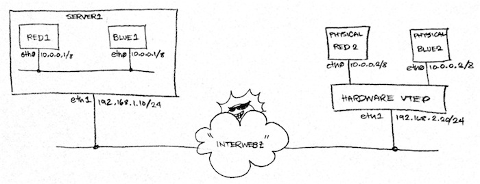
In this article, we will create the following “physical” setup using the ovs-lab:
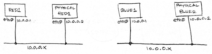
From that physical network, we will overlay two logical L2 networks:
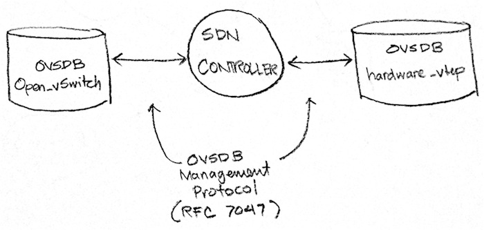
In a real-world setting, you will use an SDN controller such as NSX MH or OpenDaylight to create the above logical networks. The controller will then manipulate specific OVSDB databases on the VTEP. The database that the controller manipulates will vary depending on the VTEP’s type. If the VTEP is a hypervisor, the controller will expect to manipulate an Open_vSwitch database. If the VTEP is a hardware VTEP, it will expect to manipulate a hardware_vtep database. In both cases, the controller will manipulate the db using the OVSDB Management Protocol.
Now since the point of this article is to understand how an SDN controller manipulates a hardware VTEP, we will not be using an SDN controller. Instead, we will act as that SDN controller.
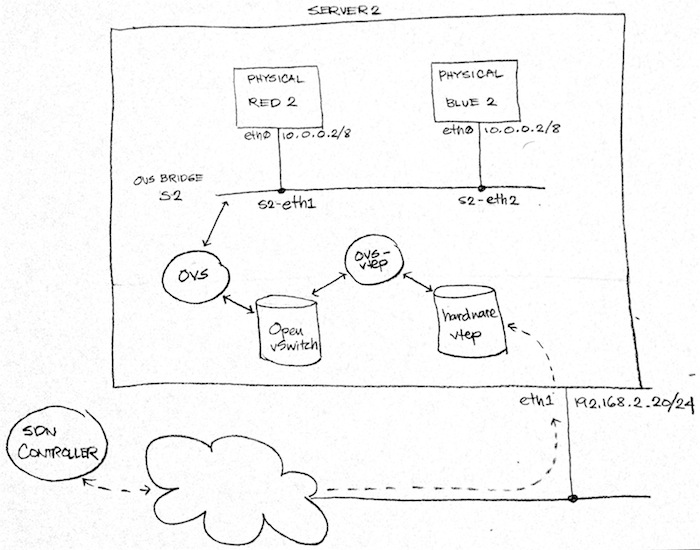
A Tiny Logistical Problem
Fig. 1 above implies that we will repurpose Server 2 into a hardware VTEP. The diagram also implies that we will need to launch two more machines, Physical Red 2 and Physical Blue 2. Finally, the diagram indicates that we need to attach both physical machines via patch chords to free interfaces in our hardware VTEP. While all of this is the ideal set-up, it’s impractical since we’re just running this set-up in our local machine. So we need to get a bit more creative.
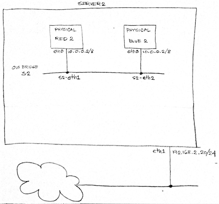
Instead of launching Physical Red 2 and Physical Blue 2 as separate VMs, we’re going to launch them as containers within Server 2 using Mininet. We will then attach them to OVS bridge S2.
NOTE: However, if you have the hardware resources to build an actual physical setup as in Figure 1 above, go for it! Just make sure to attach the ports of the OVS bridge S2 to available physical interfaces in Server 2 and then attach your actual physical servers to those physical interfaces.
We’re not in the clear yet. Remember in Fig. 3 how an SDN controller talks to a hardware VTEP via the hardware_vtep database? That means that, at this point, any configuration changes we send to our hardware VTEP would not be applied to our switch S2 because OVS only knows how to read and manipulate the Open_vSwitch database and not the hardware_vtep database!
We need some sort of translator between the hardware_vtep and the Open_vSwitch databases. Fortunately for us, the Open vSwitch project comes with a sample script that does exactly that! This is the ovs-vtep script which makes OVS emulate a hardware VTEP.
WARNING: ovs-vtep is a great way to try out hardware VTEP with your SDN controller. It’s not a great way to deploy HW VTEPs in production though since it’s just for demo/educational purposes.
Once we have the setup in Fig. 5, we can regard our “physical” network as if it’s set up like Fig. 1 (Re-displayed below for your viewing convenience!)
Hands On Time!
Now that we have an understanding of what we want to achieve, it’s time for some hands on! First, pull the latest code from the ovs-lab:
$ git pull
Next, let’s check connectivity between server1 and server2 by pinging from either side:
$ vagrant ssh server1

vagrant@server1:~$ ping -c 3 192.168.2.20
PING 192.168.2.20 (192.168.2.20) 56(84) bytes of data.
64 bytes from 192.168.2.20: icmp_seq=1 ttl=63 time=0.615 ms
64 bytes from 192.168.2.20: icmp_seq=2 ttl=63 time=0.584 ms
64 bytes from 192.168.2.20: icmp_seq=3 ttl=63 time=0.532 ms

--- 192.168.2.20 ping statistics ---
3 packets transmitted, 3 received, 0% packet loss, time 2003ms
rtt min/avg/max/mdev = 0.532/0.577/0.615/0.034 ms
If you’re unable to ping, you likely rebooted your host machine or your VMs and they lost a few network configurations. This is a known limitation of the lab that I haven’t gone around to fixing yet. In the meantime, reprovision your entire ovs-lab by running the following from your local machine:
$ vagrant reload --provision
Once reloading and re-provisioning is done, you should be able to ping server2 from server1 and vise versa. The next thing we need to do then is to instantiate red 1 and blue 1:
$ vagrant ssh server1

vagrant@server1:~$ sudo su -

root@server1:~# /vagrant/shared/lesson02/server1_topology.py
*** Creating network
*** Adding hosts:
blue1 red1
*** Adding switches:
s1
*** Adding links:
(blue1, s1) (red1, s1)
*** Configuring hosts
blue1 red1
*** Starting controller
*** Starting 1 switches
s1
*** Dumping host connections
blue1 blue1-eth0:s1-eth2
red1 red1-eth0:s1-eth1
*** Starting CLI:
mininet>
From the mininet prompt above we need to create a vxlan port on s1 and point it to our hardware VTEP at 192.168.2.20. Note that the following command must be in a single line:
mininet> sh ovs-vsctl add-port s1 vtep -- set interface vtep type=vxlan option:remote_ip=192.168.2.20 option:key=flow ofport_request=10
Finally, we will add the flows to s1:
mininet> sh ovs-ofctl add-flows s1 /vagrant/shared/lesson02/server1_flows.txt
Server 1 is now set up. Leave mininet running there as we move to our emulated HW VTEP.
Setting Up Our Hardware VTEP
Up next, we will create our “physical” servers in server2 as in Fig. 4 above:
$ vagrant ssh server2

vagrant@server2:~$ sudo su -

root@server2:~# /vagrant/shared/lesson02/server2_topology.py
*** Creating network
*** Adding hosts:
blue2 red2
*** Adding switches:
s2
*** Adding links:
(blue2, s2) (red2, s2)
*** Configuring hosts
blue2 red2
*** Starting controller
*** Starting 1 switches
s2
*** Dumping host connections
blue2 blue2-eth0:s2-eth2
red2 red2-eth0:s2-eth1
*** Starting CLI:
mininet>
Next we will create and load the hardware_vtep database in Server 2:
mininet> sh ovsdb-tool create /etc/openvswitch/vtep.db /usr/share/openvswitch/vtep.ovsschema
mininet> sh ovs-appctl -t ovsdb-server ovsdb-server/add-db /etc/openvswitch/vtep.db
We then register our switch s2 to the hardware_vtep database and indicate our switch’s tunnel IP where VXLAN tunnels will be terminated.
mininet> sh vtep-ctl add-ps s2
mininet> sh vtep-ctl set Physical_Switch s2 tunnel_ips=192.168.2.20
SIDENOTE: notice how we’re using
vtep-ctlinstead ofovs-vsctlabove? Sinceovs-vsctlonly works with the Open_vSwitch database, we need to usevtep-ctlwhich works with the hardware_vtep database.
Let’s test our work so far. Run the following command to check if we succesfully declared our physical switch S2 in the hardware_vtep database:
mininet> sh vtep-ctl list Physical_Switch
_uuid               : 2a49af81-e4bf-4937-82d5-099e5602faa1
description         : ""
management_ips      : []
name                : "s2"
ports               : []
switch_fault_status : []
tunnel_ips          : ["192.168.2.20"]
tunnels             : []
Everything should have the same value except for the _uuid field which is auto-generated by OVSDB.
Let’s now run ovs-vtep as a daemon so that our hardware_vtep settings will
be translated to OVS settings. This script comes with OVS 2.3.x which is installed
in both Server 1 and Server 2. However, that version of ovs-vtep does not work with
Mininet. I’ve submitted a patch
that fixes the problem and also provided a copy in the lesson02 directory while
that patch is waiting for approval. The latest version of the file in Github has
the fix necessary to work properly with Mininet. I’ve also included a copy of it in the
lesson02 directory.
So let’s run the modified copy of ovs-vtep. Note that the following must be in one line:
mininet> sh /vagrant/shared/lesson02/ovs-vtep --log-file=/var/log/openvswitch/ovs-vtep.log --pidfile=/var/run/openvswitch/ovs-vtep.pid --detach s2
The command returns immediately without any output. To check that the command executed
succesfully, let’s check the ovs-vtep log:
mininet> sh tail /var/log/openvswitch/ovs-vtep.log
2014-09-09T05:02:49.752Z |  0  | ovs-vtep | INFO | adding s2-eth1 to s2
At this point, you would normally have the hardware VTEP initiate a TLS connection with the controller so that the latter can start sending it instructions. However, for this exercise, because we will be manually sending instructions to the hardware VTEP, we will have it passively listen for connections instead:
mininet> sh ovs-appctl -t ovsdb-server ovsdb-server/add-remote ptcp:6633
Based on Fig. 5, the SDN controller can be anywhere on the Internet as long as connectivity can be established between it and the hardware VTEP. In our case, we’ll log in to our internet VM and send instructions from there.
$ vagrant ssh internet

vagrant@internet:~$ sudo su -

root@internet:~#
Controlling our HW VTEP with OVSDB MP
NOTE: This section will use raw OVSDB Management Protocol messages to manipulate the emulated hardware VTEP. If you need explanation on the messages being sent, Please refer to RFC 7047 and the hardware_vtep database schema.
First, let’s install some necessary packages:
root@internet:~# apt-get install jq
Next, let’s send a sample message to the HW VTEP using the netcat tool and then process the response with jq for pretty printing to the terminal. In this case, our message is a simple echo method call which should send us back the same message:
root@internet:~# echo '{"method":"echo", "id":1234, "params":["hello"]}' | nc 192.168.2.20 6633 | jq .

{
  "error": null,
  "result": [
    "hello"
  ],
  "id": 1234
}
The above only tells us that OVSDB is, indeed, running. Let’s check if we loaded the hardware_vtep database properly by asking for its schema:
root@internet:~# echo '{"method":"get_schema", "id":1234, "params":["hardware_vtep"]}' | nc 192.168.2.20 6633 | jq .

{
  "error": null,
  "result": {
    "version": "1.3.0",
  .
  .
  .
  "id": 1234
}
In preparation for attaching Physical Red 2 to the logical network that Red 1 is attached to, let’s go back to Server 1 and have red1 start pinging red2
mininet> red1 ping 10.0.0.2
PING 10.0.0.2 (10.0.0.2) 56(84) bytes of data.
From 10.0.0.1 icmp_seq=1 Destination Host Unreachable
From 10.0.0.1 icmp_seq=2 Destination Host Unreachable
...
Leave it like that and go back to internet.
Now the exciting part: let’s actually attach Physical Red 2. This command is a
bit more involved so I’ve pretty-fied it and saved to a file so that you can
study it more easily. The file is at /vagrant/shared/lesson02/attach_red2.json
and we can send it to the HW VTEP using the following commands:
root@internet:~# cat /vagrant/shared/lesson02/attach_red2.json | nc 192.168.2.20 6633 | jq .

{
  "error": null,
  "result": [
    {
      "uuid": [
        "uuid",
        "9deae9ec-a581-48a9-9790-7841c9d719ac"
      ]
    },
    {
      "uuid": [
        "uuid",
        "8a015524-1808-442a-b994-5e9b9ff30064"
      ]
    },
    {
      "uuid": [
        "uuid",
        "272e7a05-33ed-41be-bb8c-e92822691c56"
      ]
    },
    {
      "count": 1
    }
  ],
  "id": 10
}
At this point red 2 should be attached to the same logical network as red 1 and, if you head back to Server 1, you should see the ping change to:
64 bytes from 10.0.0.1: icmp_seq=1332 ttl=64 time=0.830 ms
64 bytes from 10.0.0.1: icmp_seq=1333 ttl=64 time=0.621 ms
64 bytes from 10.0.0.1: icmp_seq=1334 ttl=64 time=1.60 ms
And We’re Done!
That’s it for now. I’ll let you go ahead and experiment with attaching blue 2 to
the blue network. I’ve prepared /vagrant/shared/lesson02/attach_blue2.json for
you. There is also a get_locator_uuid.json in the same directory for getting the
UUID of Server 1 in the Physical_Locator table. Also, I recommend that you have
RFC 7047 handy as you study the two json
files. If you have any questions, please leave a comment below.
Ackonwledgements
I wouldn’t have been able to create this article without the help of the following people so a big THANK YOU to them!
- Aimon Bustardo for double-checking and fixing my many mistakes!
- Gurucharan Shetty for helping me understand ovs-vtep
- David Mahler for his very helpful videos
- The Open vSwitch Community